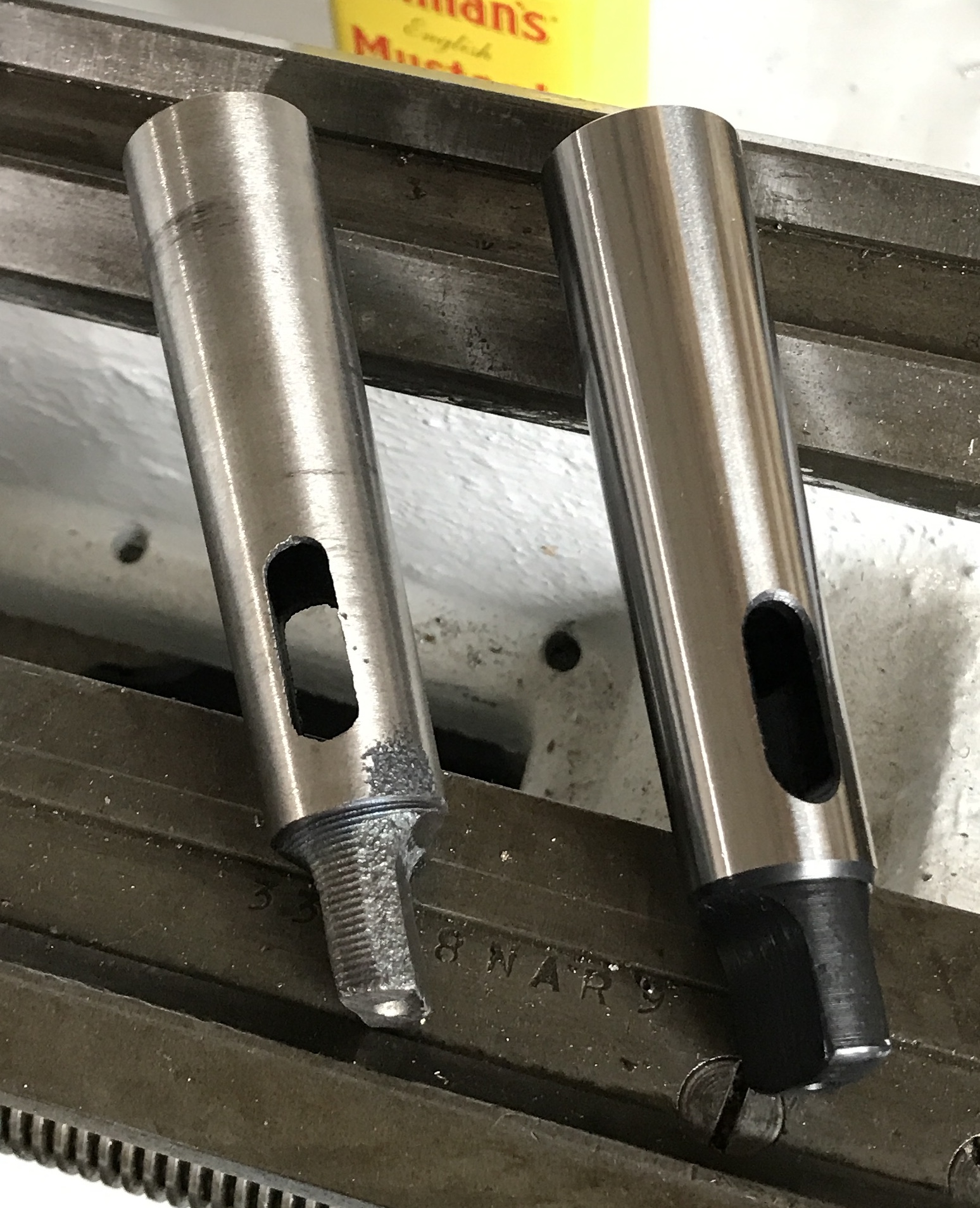
When using the gear cutter holder to make the gears for the Planetary Business Card there was a tremendous amount of chatter. So much so that Rhea thought a helicopter was landing in our yard. After examining the holder I realized the ends of the stud were not concentric with one another. When the stud was screwed into the holder it was 0.003" off. A new stud was needed.
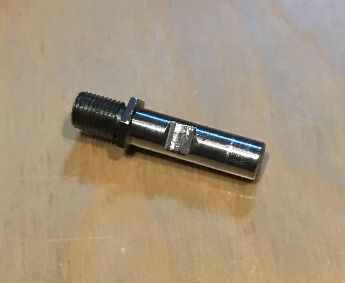
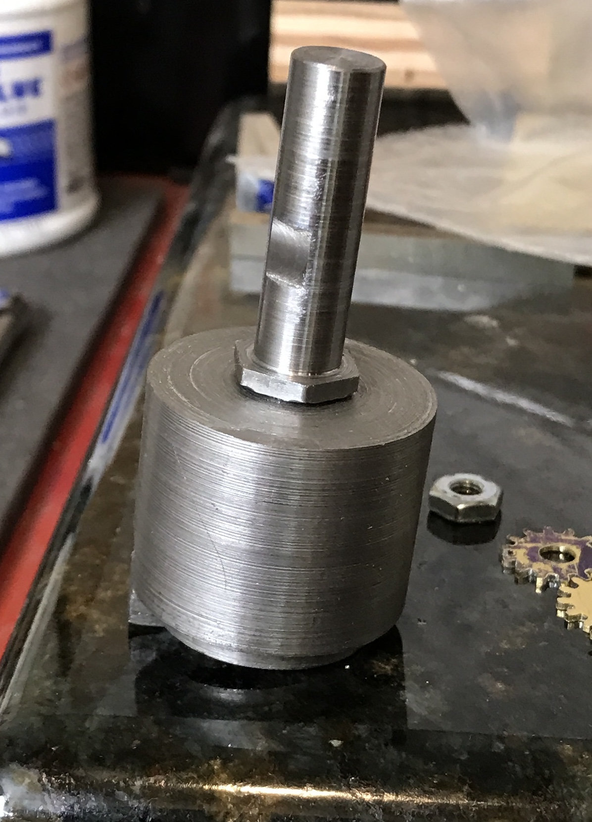
The old stud is 2" long, 0.5" is threaded 3/8-24. A length of 1/2" steel hex was held in the three jaw chuck on the South Bend lathe. One end was faced and reduced to 0.375" to fit the Sherline mill collet. This end was held in a collet on the South Bend lathe and the other end was reduced for 0.5" to 0.373" insuring concentricity. I only have a large die for 3/8-24 threads, so it had to be threaded by hand. The threading went easily, but the threads were started crooked! The photo doesn't do this mistake justice.
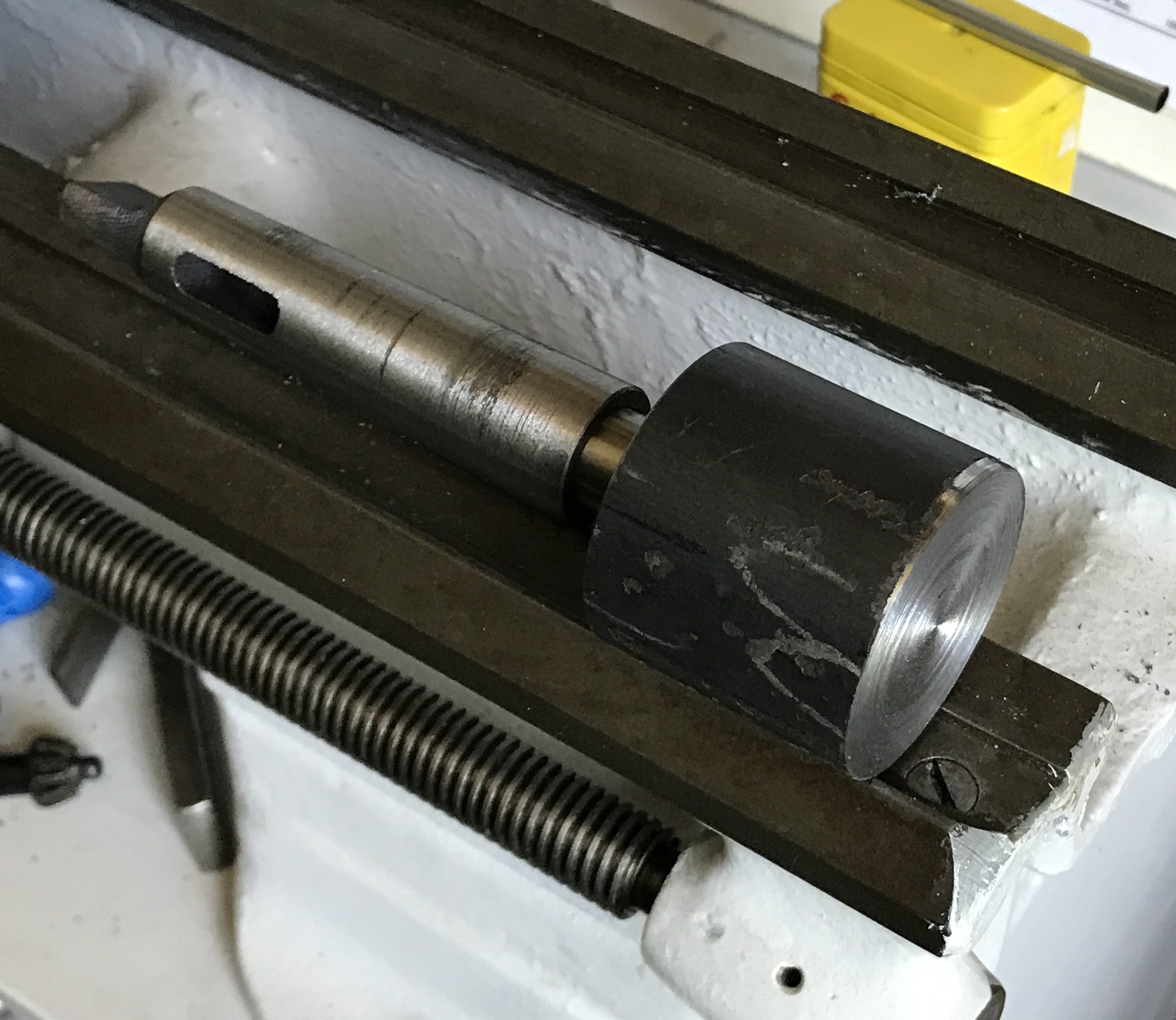
A tailstock die holder for the South Bend was needed. The large dies in my stash are 1.5" in diameter. A length of 2" steel round was found. A 2" length was cut off with the horizontal band saw. This was held in the chuck, faced and drilled. It was first drilled with a center drill, a 1/4" drill and finally with a Q drill to a depth of 5/8". I have a MT2 taper with a 3/8-24 threaded adapter. The hole was tapped with a 3/8-24 tap started in the lathe. Tapping was finished in the vise. After cleaning the chips out of the hole the taper fit nicely.
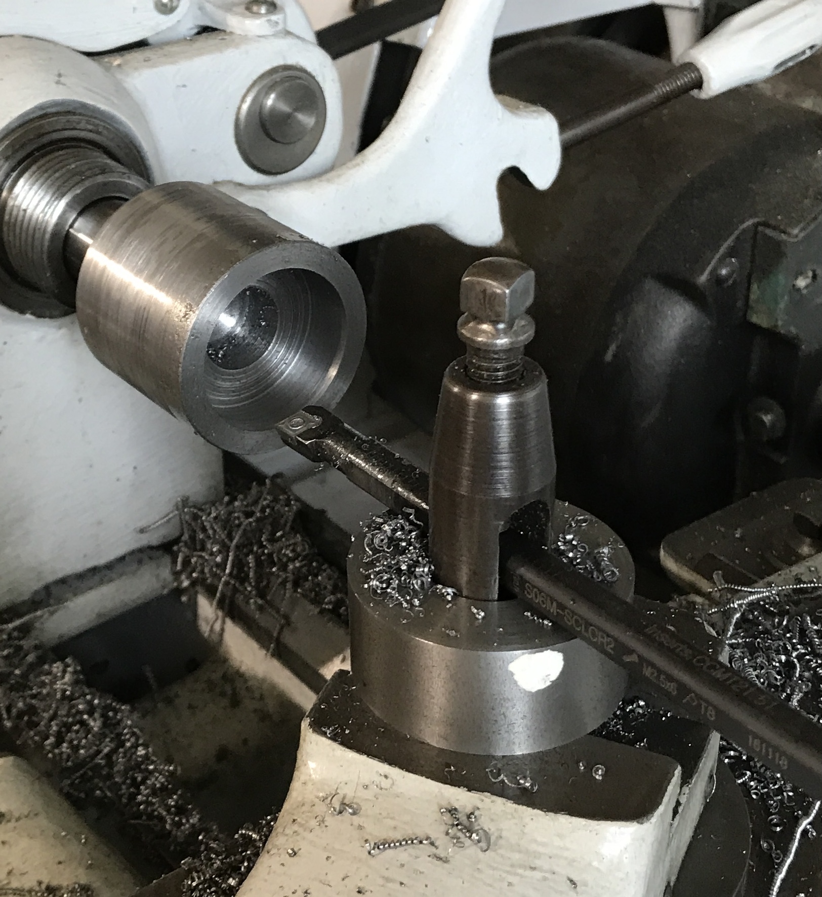
In order to maintain concentricity the MT2 taper was installed in this 2" length of steel round. After searching for literally two hours, the MT2 to MT3 adapter was located. It is from China and the finish left a lot to be desired. The adapter was installed on the MT2 taper and the whole thing pressed into the spindle. The steel was faced. As this proceeded the taper kept coming loose from the spindle. Eventually, the part was faced. The next task was cleaning up the outside. I was unable to do this without the POS taper adapter coming loose!
A new taper adapter was purchased from Shars. The difference in quality is quite apparent. The Shars tool also includes a certificate of inspection.
The steel round was screwed onto the MT-2 taper and this was inserted into the adapter. The whole was inserted into the spindle. The part was refaced, and the outside turned sufficiently to clean off the corrosion. The new taper adapter held solidly throughout all of the operations. The part was center drilled and drilled up to 3/4". The drilling went 1 1/4" deep. The part was bored out to 1 1/2" ID to a 1/2" depth.
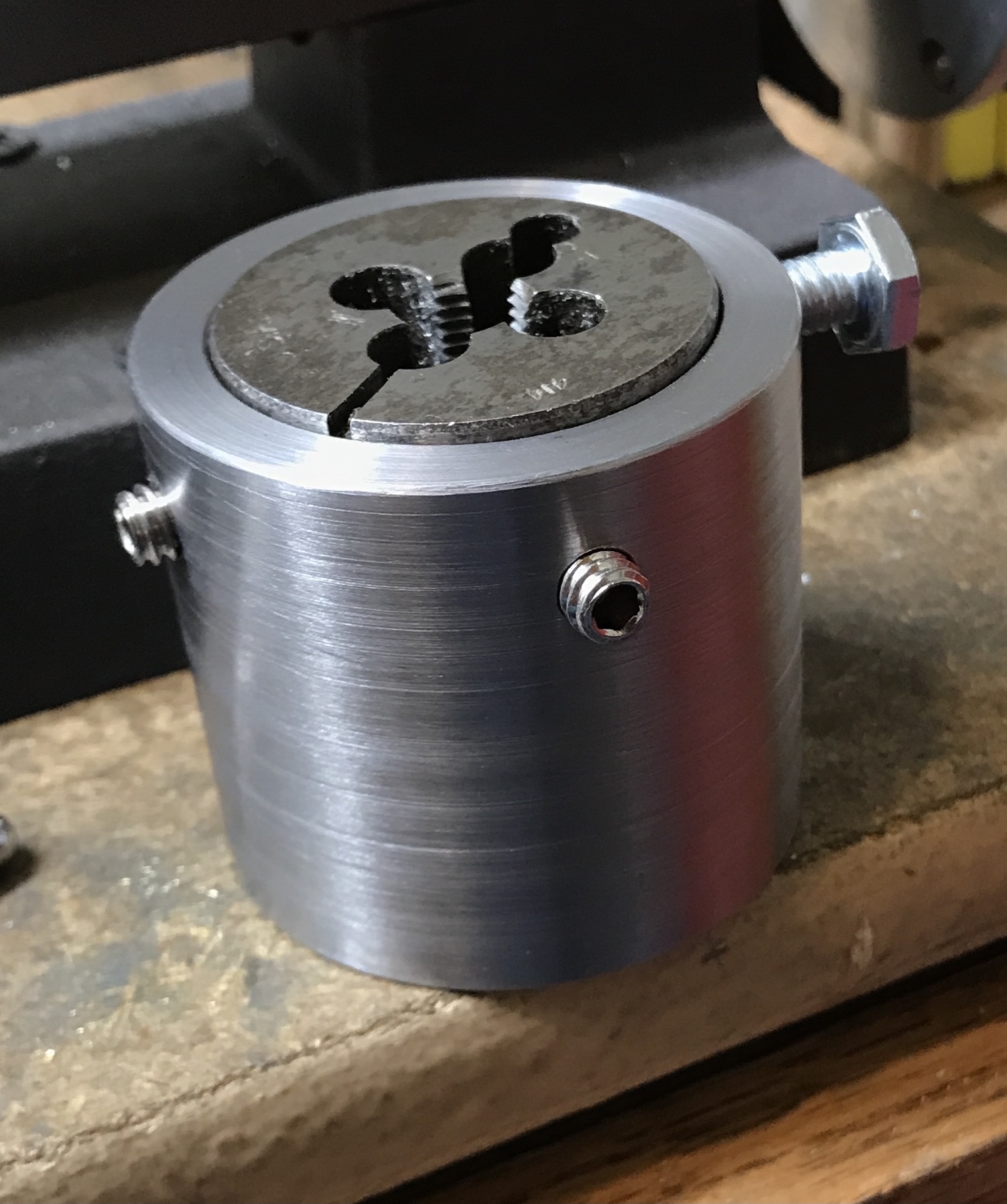
After boring the part was held in the vise attached to a four-sided indexing block. Holes were drilled and tapped. Unfortunately, the distances from the edge were not close enough. A 1/4-20 screw was cut off and the end tapered. The die is tightly held in the holder, but it is difficult to align. Must have been made in China!
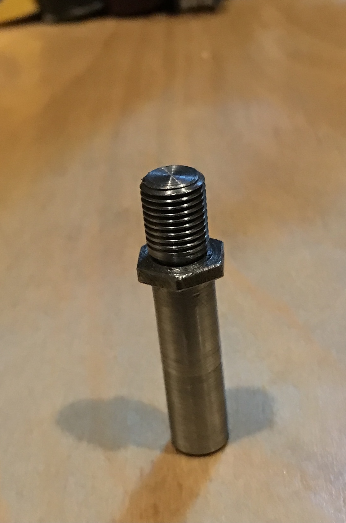
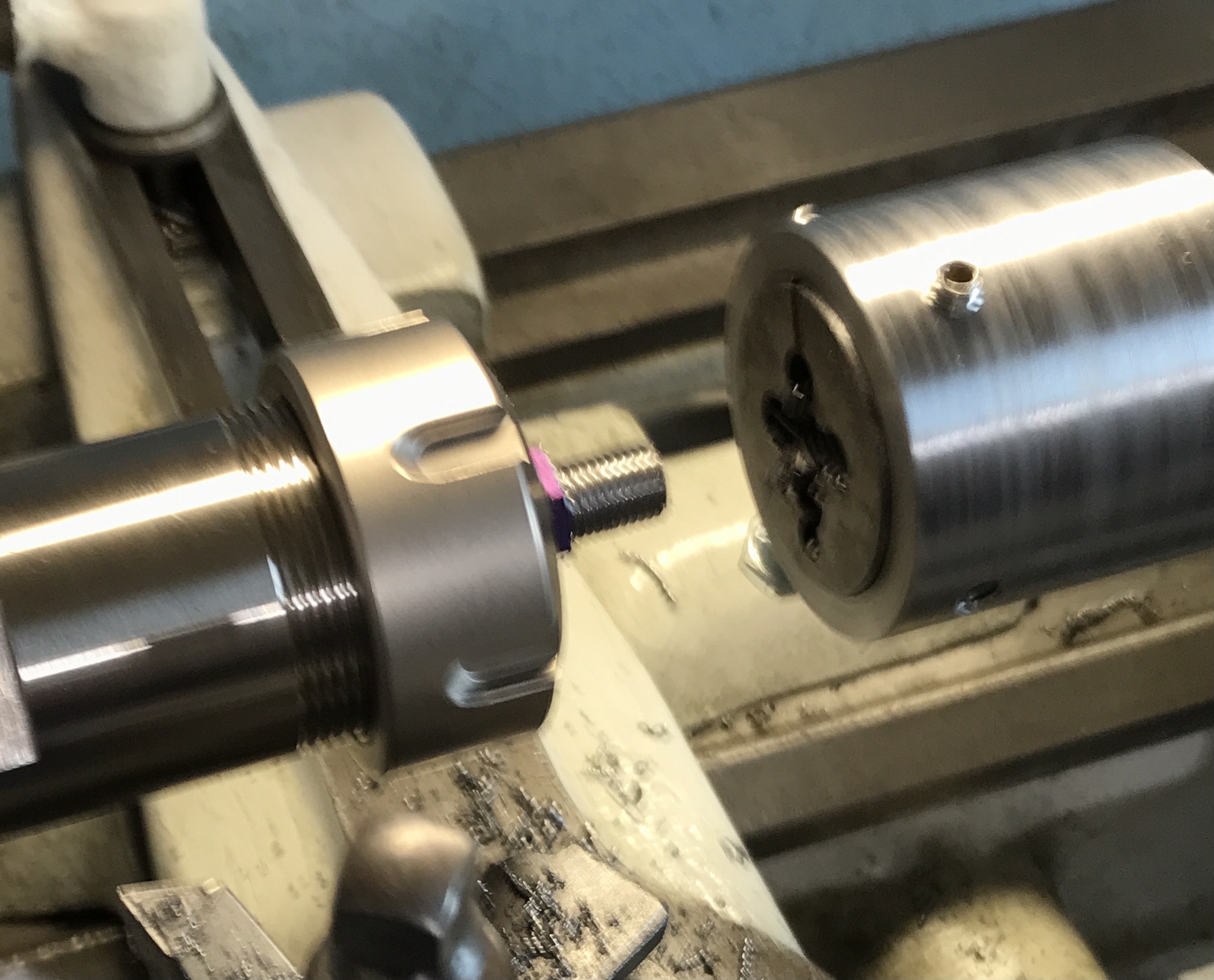
This time all went well using the South Bend lathe. The long, 1 1/4", end was reduced to 0.375" and a sliding fit in the Sherline milling collet. This end was held in a collet and the opposite end was reduced to 0.374" for 1/2" leaving about 1/16" of hex. The tailstock die holder worked phenomenally well to thread this end. The headstock was turned by hand, while pressing the die against the end of the stock.
A 1/4" flat was milled on the long shaft about 3/8" from the hex for the collet's set screw. It was held in the vise for milling by screwing it into the gear cutter holder and holding that. The flat was milled about 0.025" deep.
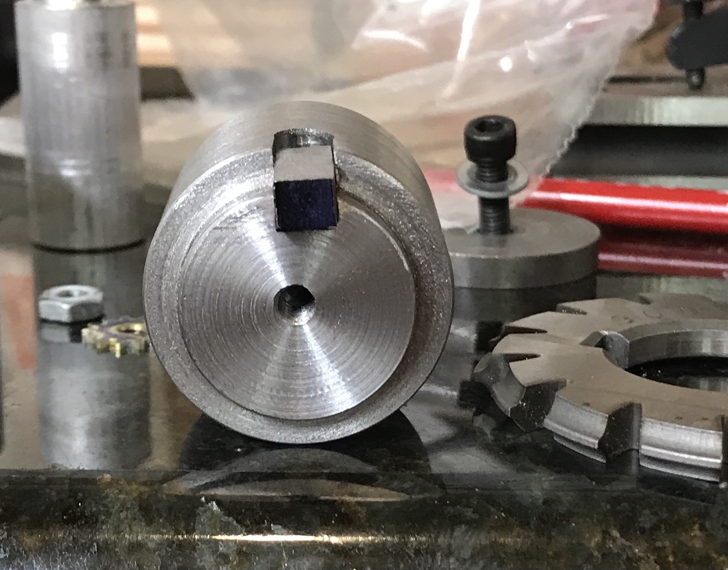
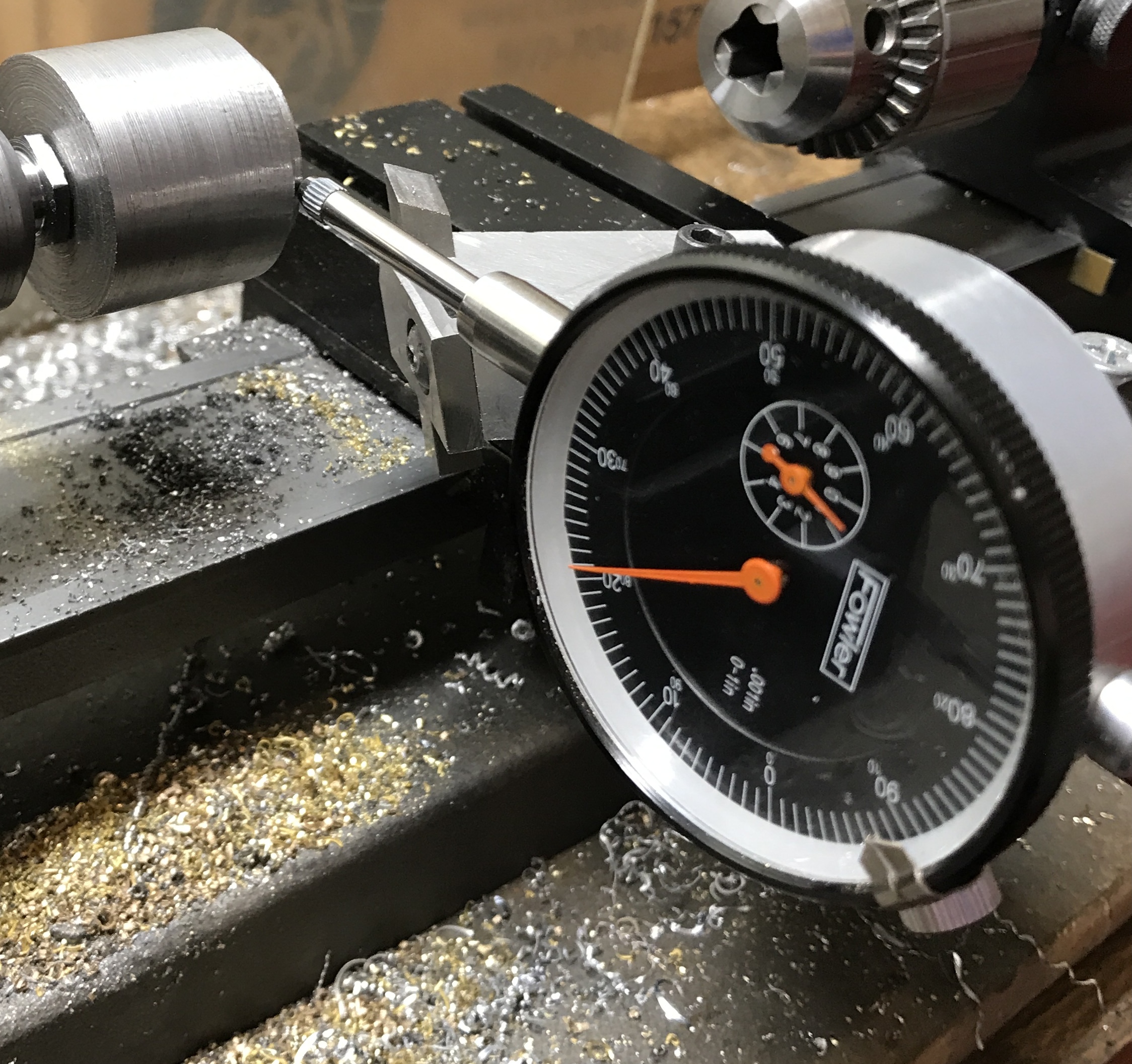
I decided to check the runout of the gear cutter. The new shaft was mounted in the gear cutter holder and a gear cutter was mounted. The shaft was held in the Sherline collet attached to the lathe's spindle. The tip of the dial indicator was pressed to the high spot of a tooth. The face was zeroed. The teeth varied by at least 0.015"! The shaft is no longer responsible for the observed error. The gear cutter was removed and the holder was tested for error. The radius of the inset was off by 0.020"! Some meditation is in order before remaking this gear cutter holder.
A 1 1/2" length of 1 1/2" steel round was cut off with the bandsaw. This was faced on the South Bend lathe. It was drilled up to a C drill and tapped 3/8-24. The incompletely finished holder was screwed to the new shaft. When this shaft was screwed into the holder and placed in the Sherline chuck (too hot in the garage) the holder was really out of alignment. A few days later the shaft was held in a 3/8" collet in the South Bend. The holder was faced and the outside reduced until it was concentric. The first 1/8" was further reduced to 1.000" so it was a sliding fit in the gear cutter.
After some repair work (plugging a hole with a press fit shaft) The end was faced again and a hole was drilled on center with a #21 drill. The hole was tapped 10-32 for the screw that holds the cap in place. With the holder at a testable stage, it was checked for concentricity. The gear cutter was put in place and the cap tightened. The gear cutter showed about 0.010" of runout. Checking the holder showed the same 0.010" of runout!!! Somehow holding the shaft in the collet for the South Bend is not the same as holding it in the Sherline collet. The holder will need to be recut on the Sherline.
The reduced section on the holder was cut off with a series of passes on the Sherline. There was a tremendous amount of chatter that continued through the entire operation. A new section was reduced to 1.000" to fit the gear cutter. It was made approximately 0.125" long. A file was used to deburr the new edges. The installed cutter was measured. It still seems to have some residual error! The cutter was measured from the outer edge of the hole to the tip of a tooth. These measurements varied consistently from 0.661 to 0.667"! That is the current error when the cutter is installed. The holder is accurate, but the cutter sucks!
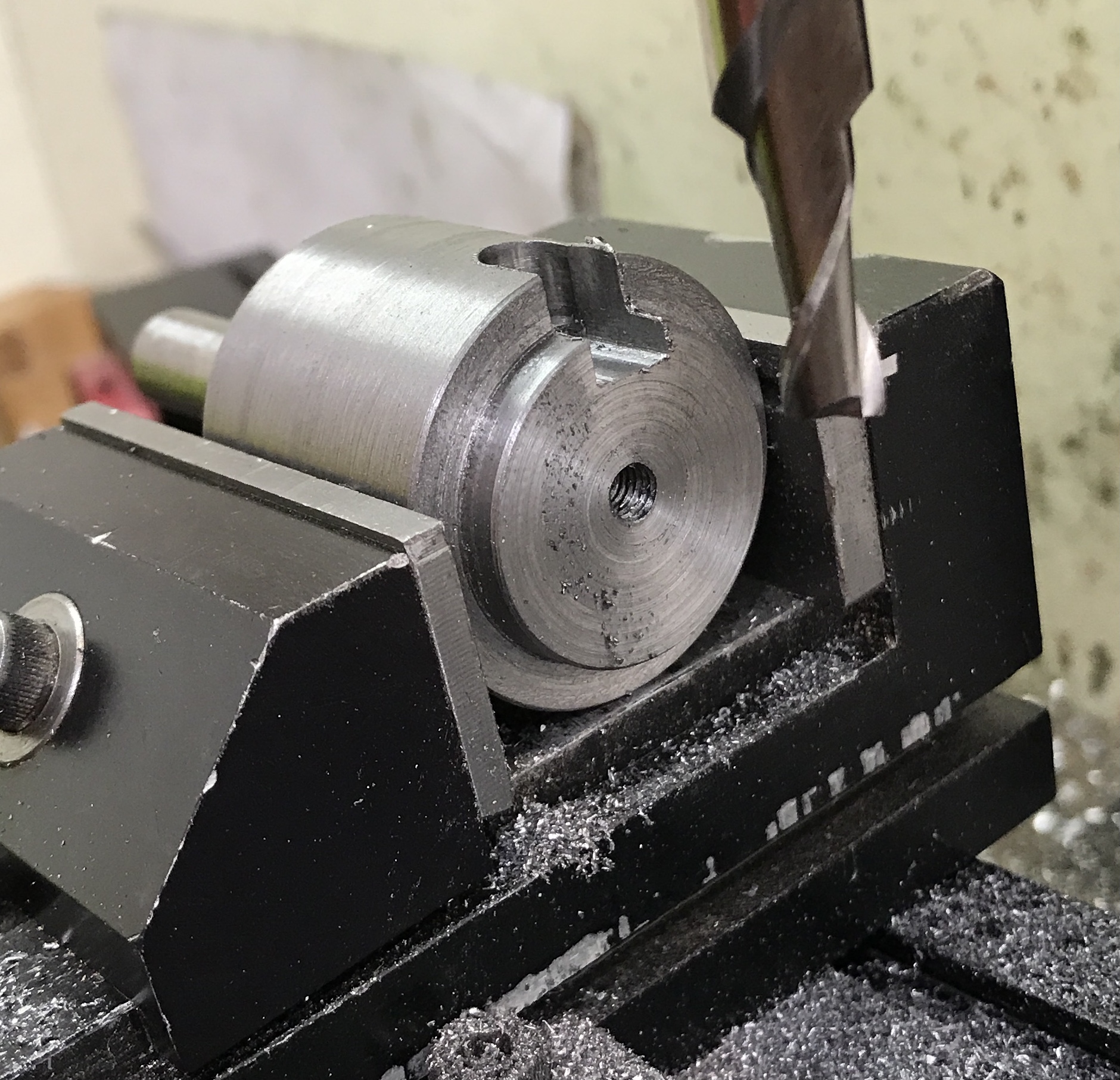
The holder was secured in the vise and drilled on center 1/2" in from the end with a 1/4" drill. A 1/4" end mill was used to cut a slot in 0.015" increments to a 1/8" depth into the registration face. For some reason the slot is slightly angled!?! A 1/4" X 1/4" X 1/2" piece of steel was cut from a scrap. After some filing the cutter fit tightly on the holder with the steel key installed. The key was glued in with red Loctite.